
Most people realize the tires on their car are out of alignment when they feel the vibration or the vehicle wandering all over the road. It affects fuel efficiency and causes tires to wear more quickly. The same things happen to belt conveyors, even if it seems to be running fine. Shiny rolls are a good indication that idlers are fighting each other due to misalignment to the belt line.
Idler misalignment causes conveyors to miss-track and the idlers and belt to wear. Even if the effects are invisible, power and money could be saved with a one-time tuneup.
Aligning idlers means setting Aei of Figure 1 to zero. Slots are provided in idler frames to allow easy adjustment for this. The hard part is to know which way to adjust them. This is true when idlers are first installed and most idlers are never moved after that. Realigning or replacing idlers has the same difficulty. Sometime idlers are sighted in and then “knocked” to tracked the belt. Measuring to the adjacent idler only provides the same misalignment for both. At best, tape measures are used on the idler footpad to cross measure the frames to the stringers. Both measures may incorrectly assume the frames were built precisely.
The best alignment is when the belt and rolls are used in the measurement. Custom-built jigs necessary for this are typically only used on the largest conveyors. The center roll is the hardest to get at but the best to use. This is because the three rolls may not all be in line and it carries most of the belt and bulk weight so it has the most influence on steering and power loss.
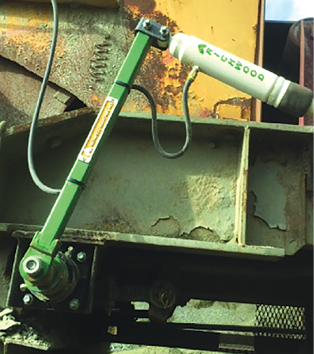
Alignment measurement is a problem because the important features, the belt line and middle roll centerline, are remote from each other. This prompted the development of a new Alignment Verification Rig (AVR). (See Figures 2 and 3 and avr4idlers.com.)
This device uses magnets to quickly clamp to the idler roll and uses a rotatable laser to locate a plane perpendicular to the roll centerline. The angular misalignment can then be seen by comparing the laser plane location to two points along the belt edge. This allows fine tuning idler alignment after the belt is installed, even after many years, as long as the belt edge is reasonably unworn. Measuring to widely spaced locations on the belt inherently gives very good accuracy and indicates which way one footpad of the idler should be moved relative to the other. The same approach can be used in new construction if another laser or piano wire is used to indicate the belt line.
Figure 1 – Belt conveyor top view showing the idler angular misalignment (Aei).
Idler Alignment and Conveyor Operation
Each idler set has its own alignment (Aei) that affects its rollers’ misalignment force and wear life. Together, misaligned idlers accumulate to significant energy loss. Idler roll alignment can also include variability in manufacturing. Even careful frame installation doesn’t address this so the rolls themselves are the key to optimum installation, though it’s very hard to access their axes. Since the center roll carries the most load, aligning to it has the most benefit. The AVR accesses this roll to show its alignment accurately, quickly and easily from one side of the conveyor. Its low cost makes it even more practical.
Why Does My Belt Track Fine? While idler angular misalignment can have a strong influence on belt lateral tracking, individual rolls and idlers usually counteract one another by being angled in both directions so decent belt tracking despite misalignment comes at the price of wear and energy loss. In addition, gravity tries to center the belt in the trough so mistracking is not a good sign of misalignment.
How Well Are My Idlers Aligned? Idler alignment is identified as one of four main friction losses in CEMA’s belt book, sixth and seventh edition. Misalignment design categories show average conveyor idlers have misalignments ranging from 0.25 to 1.5 inches (in.) depending on the application and installation. This range is wide because good alignment requires care and the right tools. In addition, the effect on the bottom line has been underestimated over the years.
To properly estimate wasted power, measure the idler spacing on both stringers for a section of five to 10 idlers. Subtract the spacing of one side versus the other for each space. Some of the differences will be negative and some positive. Adding the differences (keep + and -) and dividing by the number of idler pairs usually yields a low number, but make them all + before adding and a higher value will be seen. The first average is the net mistracking effect and the second is an estimate of the misalignment that causes wear and power loss.
It is straightforward to estimate each conveyor’s idler misalignment and the money lost to show one benefit of realigning idlers.
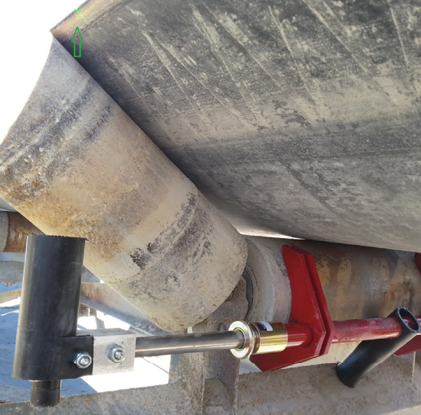
Figure 2 – Alignment Verification Rig (AVR) mounted to an idler and set to belt edge. Note gold colored lock collar.
Calculating Power Lost and Power Cost
As an example, a 36-in. belt full of coal and with an average Aei=.25 in off alignment will be used. That is, one side of the idler is 0.5 in. ahead of the other. Divide that by the width of the idler frame. Typically that’s belt width plus 9 in., so 0.5/(36+9) = 0.011 for the ratio of sideways movement to forward belt movement. (The AVR allows a direct measurement or use the above estimate).
The cost of idler misalignment can be estimated as =Idler misalignment/Idler bolt spacing*friction factor*(Conveyor load per unit length + belt weight per unit length*2)*conveyor length*belt speed*hours per year*power cost per kWhr.
For example, in Imperial units;
(1/2-1/16)/(36+9)*0.5*(1,600*2,000/60/600+10*2) *600*1,500*.000023*3,000*$0.10= $3,230/year for a 1,500-ft conveyor.
(or, download a spreadsheet calculator from avr4idlers.com).
Longer and bigger belts save more. This and the intangibles that go with it only cost a few hours from the maintenance crews. Bottom line, the longer the conveyor and the worse the idlers are aligned, the more money that will be saved with improved alignment.
Conveyor Power
Conveyor power usage has been a topic of interest ever since the first conveyors were used. Conventional wisdom, supported by continuing measurement and research since then, understands the power supplied by the conveyor drives is the sum of several almost independent “main resistances.” Individually, or as a total, their effective friction factors can be compared by dividing it by the weight of the belt and bulk load. The total friction can vary from 0.040 to 0.010 for the best conveyor designs.
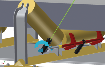
Figure 3 – Rotation of the AVR laser shows idler angular alignment by comparing two points along the belt edge.
Much of the world estimates the main resistances with a single overall friction factor, based on history, though each of the main resistances is affected differently by the specific material, design and construction details. The Conveyor Equipment Manufacturers Association (CEMA) has long recognized the individual impact of various parts and configurations and include a set of power prediction equations addressing each in its “Belt Conveyors for Bulk Materials,” especially in the sixth edition in 2005 and the seventh edition. This design and analysis approach has proven to provide a better foundation for design accuracy and optimization for complex conveyors, especially since computers have allowed the many calculations and checks needed for thorough design over a wide range of cooperating conditions.
The main friction losses and their relative contributions as percentage of total power on a flat conveyor are:
- Belt rubber indentation rolling resistance from the belt internal hysteresis. It is affected by load, temperature and compounding of the durable, filled rubbers used on conveyors (25% to 80%).
- Idler alignment from imperfect angular alignment during installation and manufacturing (10% to 50%).
- Idler rotating resistance from the design and manufacture including seal and temperature sensitive grease drag (10% to 60%).
- Bulk material friction due to internal movement from belt sag between each pair of idlers, especially with belts with fabric carcasses and at lower tension (1% to 55%).
In addition, miscellaneous component can contribute from 2% to 10%. Inclines or declines dominate the power loss categories and belt tension when the slope is much greater than 5°, but the above still have an absolute effect on power.
For long conveyors, friction has a major impact on the capital costs due to the motor size, but, more importantly, due to the required belt strength and/or the number of idlers needed to control sag. The importance of each varies widely and is only known from detailed calculations and measurements. However, from an operating cost point of view, each impacts the energy cost, a major operating cost. Other friction from pulleys, skirtboards and other accessories is important for short conveyors but also vary significantly.
Detailed calculations for the individual resistance categories are provided in CEMA’s Belt Conveyors for Bulk Materials’ sixth and seventh editions and used in many modern conveyor designs with software such as Overland Conveyor’s Belt Analyst. Figure 4 shows the power breakdown from Belt Analyst of one example. The size of the pie pieces varies widely depending on the wide range of operating, design and installation details.
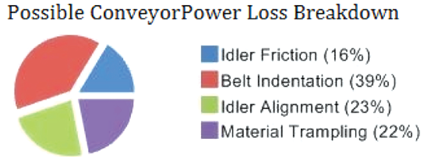
Figure 4 – Example of ‘main resistance’ breakdown for a conveyor designed by CEMA’s Chapter 6 methods with Belt Analyst.
More on Idler Alignment
As shown above, idler misalignment can have a significant impact on the motor power required to run a conveyor and the belt strength required to carry the tension. Idlers are misaligned in several ways, but this article concentrates on the angular installation deviation from 90° to the direction of belt travel. In reality, a small error inevitably exists, but knowing and managing the amount of misalignment is part of thorough conveyor design and construction.
Any angular misalignment increases the friction and power requirements on the conveyor system by introducing transverse slip between the idlers and the belt. The greater the angle from the ideal idler axis to the actual idler axis, the greater the transverse slip introduced. When the idler is not rolling in exactly the same direction as the belt, an additional friction force is created and seen as an energy loss that the motor has to overcome. This has been measured by the author to be a linear effect of the misalignment angle and load on the idler and is additive for the number of idler sets along the length of the conveyor. The more friction forces and losses created the more power required for running longer conveyors.
Other misalignment types, specifically vertical and lateral misalignment between idler sets, can negatively affect the conveyor in terms of varying idler loads and belt tracking, but they do not impact the required power like the angular misalignment is capable of. Forward tilting of the idler set, which is sometimes done intentionally to aid belt tracking, or using hanging garland idlers, can also have a similar misalignment and significant negative impact on the required power for a conveyor. Polymer rolls have a lower friction coefficient so have less misalignment loss.
While misalignment of the individual rolls of each idler is also introduced when fabricating the idler frames, this should be a significantly smaller error if manufacturers use precise jigs. In comparison, idlers are installed on varying structures in uncontrolled environments. In any case, the center idler roll carries the most load so misalignment from manufacturing variation is minimized by aligning to it, though its axes are difficult to access. Alignment commonly depends on tape measurements on relatively inconsistent idler features between adjacent idlers.
In many cases, during commissioning or with training idlers, the idler sets are slightly, but intentionally misaligned to make the belt track properly. The intentional misalignment creates additional friction forces from the transverse slip to push the belt in the right direction. The need to intentionally misalign during commissioning may be a sign of poor idler or structure installation to counteract other misaligned idlers. Aligning the center roll of each idler to the belt line prevents accumulation of errors and provides.
If idler alignment is planned before construction, and each is installed within specification, the conveyor requires less power to run, which allows the use of smaller motors and lighter belts, decreasing initial and operating costs of the conveyor. Wear and reliability follow as well.
Existing conveyors can be upgraded and often benefit in the same ways by realigning the idlers. The idler AVR described at avr4idlers.com makes this process accurate and cost effective.
Allen V. Reicks has spent much of his career at Overland Conveyor Co. and Precision Pulley and Idler. He is the primary author of Chapter 6 Belt Tension and Power Engineering of the Conveyor Equipment Manufacturers Association (CEMA) “Belt Conveyors for Bulk Materials.” He can be contacted at al@avr4idlers.com.
Martin Releases Conveyor Safety Reference Book
 Martin Engineering, which has become well known for its conveyor safety advancements, has published what it has called the world’s first aggregation of global best practices dedicated to reducing conveyor risk and injuries.
Richwood Makes a Clean Impact