

Ultra-thick seams in this article refer to those equal to or greater than 6-m (20-ft) thick, but the majority are seams that are 7-m (23-ft) thick. For seams that are this thick, there are two major mining methods; one is top coal caving that was first adopted in the 1980s, while the other is the ultra-thick whole seam one-slice longwall mining that was launched at the end of 2009.
In top coal caving mining, the bottom 2.5-4 m (8.1-13.1 ft) of the seam is extracted by the conventional longwall mining method and the remaining roof (top) coal is naturally caved behind the shield. In this method, there are two armored face conveyors (AFCs) at the longwall face, the front one located in front of the shield legs is operated like conventional longwall mining, while the rear one is located behind the lemniscate links and under the caving shield. Each caving shield has a door for drawing the broken top coal onto the rear AFC. Top coal drawing can either follow every longwall cut or every other or more cuts. The ratio of mining height-to-top coal caving height ranges from one to three times the mining height at the bottom. The disadvantages of top coal caving are that the recovery rate of top coal at both ends of the face is very low and the coal left in the gob is the source for spontaneous combustion.
Therefore, the ultra-thick whole seam one slice longwall mining was developed to increase the recovery rate and safety of ultra-thick coal seams in 2009. Up until then, top coal caving was almost exclusively used for the extraction of ultra-thick seams. At the end of 2009, China successfully developed the 7-m two-leg shield (See Figure 2) and put them into production at the Bulianta mine (See Figure 2) where the coal produced was transported via an underground belt conveyor to the nearby coal-to-liquid (CTL) plant for making diesel fuel. Subsequently, the whole seam 7-m mining height longwall was also adopted by the neighboring Shang Wan and Daliuta mines. Those three mines are producing from 15 million to 25 million mt annually. This article will feature the typical mine layout and mining technique used in these three mines.
According to statistics compiled by ZMJ (Zhenghou Mining Machinery), there are now approximately 60 longwall faces employing the ultra-thick whole seam one slice mining method of 6 m-7 m (19.7-23 ft) thick. The shields are all made by Chinese manufacturers with ZMJ accounting for more than 90% of the market. The shearers are either domestic-made or imported, mainly Joy and Eickhoff, while AFCs are also either made in China or imported, mainly Caterpillar. For this article, the first three authors toured and studied all the mines with annual production of more than 10 million mt in Figure 1, plus three mines in southeastern Shanxi Province and northwestern Henan province.
Due to its favorable geological conditions, both state and private investors converged in the Ordos coalfield in the past 10 years and opened more than 1,000 coal mines. Metropolis such as Ordos and Dongsheng popped up overnight in the middle of desert, creating hundreds of “coal boss millionaires.”
Geology
The Ordos coalfield located in the semi-arid western region of China was discovered in the early 1980s with more than 200 billion mt probable reserve, accounting for approximately 25% of the Chinese total. It is listed as one of the seven largest coalfields in the world. Its coals are uniform in thickness and near horizontal, low in sulphur and ash, high in heating value and shallow in depth (as compared with other coalfields in China). Undoubtedly, it is the key source location of coal energy for future development in China.
Figure 1: The Ordos coalfield, Inner Mongolia, China, showing the major coal mines operated by Shenhua Coal Group, the world largest coal company producing more than 400 million metric tons in 2012.
The Ordos coalfield is a monosynclinal structure. Coal seams are shallower, 0-100 m (0-328 ft) deep in the northeast and dip toward the southwest where it reaches more than 400 m (1,312 ft) deep.
In the three mines where the ultra-thick whole seam 7-m single-slice longwall mining is employed, there are 5-10 minable coal seams ranging from less than 1-m to 9.4-m (<3.3-31 ft) thick with seam interval of 2.6 m-110 m (8.5-361 ft). All seams are either flat or dip less than 3˚. Major coal seams being mined at the three mines of interest vary from two to three seams. The depth of the top seam being mined in each mine varies from 80 m to 280 m (262-918 ft).
The coals in these three mines are of good quality with low sulphur (<1%), low ash (6-9%), low in phosphorous, very low methane, median water content (10-16%), high volatile matters (35-40%) and median heating value (10,260-12,600 BTU). However, they are predisposed to spontaneous combustion.
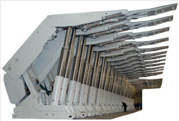 Figure 2: Typical 7-m (23 ft) high two-leg shields manufactured by Zhengzhou Mining Machinery (ZMJ), the largest shield manufacturer in China and the world, producing annually more than 22,000 units of various types of shields.
The overburden in the Ordos coalfield has the following common features: the bedrock above the coal is thin; it is overlain by thick loose or unconsolidated sands or pebbles; and the overall depth is shallow. So if the mine is not properly designed and operated, severe hazards, such as the entire overburden from the mine level to the surface collapses suddenly, or the loose sands quickly flood the mine once the thin bedrock is accidentally broken through. This problem may occur and actually has happened in the past. This type of hazard is especially critical in the 7-m high longwall operation. This is one of the subjects of the authors’ current research sponsored by the Chinese Natural Science Foundation.
The roof consists of alternating layers of claystone, sandy claystone, clay sandstone and powdered sandstone. In particular, the roof stratigraphic sequence in ascending order from the coal top is sandy claystone (false roof), 0.12-m (0.4 ft) thick; claystone (immediate roof), 3.4-m (11.2 ft) thick; and sandy claystone or powdered sandstone, 44-m (144.3 ft) thick. The loose sands above the bedrocks ranges from 10-m (33 ft) to 60-m (197 ft). The immediate floor is claystone or powdered sandstone, 0.5-m (1.5 ft) thick. In general, with well-developed planes of weakness, the roof caves properly with moderate periodic weighting, even though some of the rock units are fairly thick. When dry, the floor is firm enough for normal shield advance and pan push. On the contrary, when wet, the floor can be weakened dramatically. The sandstone can be clay-cemented or calcite-cemented.
Geological anomalies such as faults with offset up to 1.7 m (5.6 ft) are found in some mines. However, their location and spacing rarely adversely affect normal panel layout.
Mine and Panel Layouts
All mines are located on both sides of the approximately northwest-southeast oriented Wulan Mulun River (Fig. 1). Mine and panel layouts are similar to those employed at U.S. longwalls with a few modifications/improvements. From the surface face-up area, three drift tunnels are driven horizontally, some by a full-face tunnel boring machine (TBM) 7.3 m (24 ft) in diameter, in the roof for some distance and then continue to dip down about 5˚, until they reach the seam level. From there, the mains consist of three to four entries. Panels are developed by two-entry gateroad perpendicular or at some angle to, and on either one or both sides of, the mains.
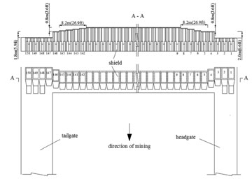
Figure 3: Shield layout and shearer’s cutting profile illustrating the transition zone’s 2.8-m (9.2 ft) height difference between shearer’s full-seam cutting height 7 m (23 ft) at mid-panel and entry height 4.2 m (13.8 ft).
The panels are 300 m-310 m (984-1,017 ft) wide by 4,300-6,000 m (14,104-19,680 ft) long. The one row of chain pillars are 15- to 20-m (11.7-65.6 ft) wide by 50- to 85-m (164-279 ft) long.
Each longwall needs either one or two units of continuous miner (CM) units. Entries are driven by conventional Joy CM’s or Voist-Alpine ABM miner-bolters. The rate of development ranges from 800 m (2,624 ft) to 1,500 m (4,920 ft) per month. Entry dimensions and support pattern vary slightly not only from mine to mine, but also depend on entry function within a mine. The headgate and tailgate are rectangular in shape, 5.5- to 6.1-m (18-20 ft) wide by 4- to 4.2-m (13.1-13.8 ft) high. They may or may not be of the same dimension. Note the height of gateroads is about 2.8 m to 3 m (9.2-9.8 ft) shorter than the longwall cutting height. The large offset in entry height and panel cutting height was considered necessary in order to make the rib stability manageable.
The large offset between entry height and panel cutting height demands a special shearer cutting sequence and shield layout. Figure 3 shows that the mid panel from Shield No. 9 to No. 141 is 7 m (23 ft) full seam height cut; from Shield No. 8 to No. 4 (or from No. 142 to No. 145) is the transition zone where the cutting height is reduced from 7 m (23 ft) to 6.2 m (20.3 ft). So the offset between Shields No. 3 and No. 4 on the head side (and Shields No. 146 and No. 147 on the tail side) is 2 to 2.2 m (6.6-7.2 ft). In order to prevent this large exposed vertical offset from spalling, Shields No. 4 and No. 146 are equipped with a specially-designed side shield to protect it.
For the 310-m (1,017 ft) wide face, the move time for the 155 units 70-ton shields is seven to eight days.
Face Equipment
Similarly, the types and layout of equipment resemble those used in U.S. longwalls (See Figure 4). However, there are several notable differences including: (1) The 7-m (23 ft) high shield with the largest yield load in the world, plus the use of side shield to stabilize the large vertical offset at both ends of the face; (2) all roadways are paved with concrete floors of 200-mm (8-in) thick or more for convenience of all rubber-tired transportation vehicles including passenger cars; (3) panel belt conveyor and mule train are laid side by side in the headgate even though some headgate are only 5.5-m (18 ft) wide; (4) Self-advancing entry supports are installed immediately outby the headgate and tailgate T-junctions (See Figure 5) to cope with the abutment pressure; and (5) the AFC tailpiece is extended into the tailgate partially or fully making it necessary to remove the tailgate supports ahead of the advancing panline, if the self-advancing outby entry supports are not used.
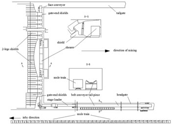 Figure 4: An example of face equipment layout.
The double-ended ranging arm shearers with a lump breaker are either Joy’s 7LS8 or Eickhoff SL1000. Their specifications are: mining height of 3.5-7 m ( 11.5-23 ft), drum diameter of 3.5 m (11.5 ft), cutting web of 865 mm (34 in), maximum traveling speed of 25m/min (82 fpm), 3,300 volts power supply with total power of 2,925 KW (3,920 HP). Bidirectional cutting is used exclusively. Daily face advance averages 15 m (49.2 ft).
AFCs are made by Cat. Their specifications are double center chain strand 60 x 181 mm, running at 1.59 m/sec (313 fpm) and powered by three motors a 3 x 1,600 KW (3×2,144 HP). The pans are each 1,200-mm wide x 2,050-mm long. High voltage electric, 3300 volts, is used. Maximum carrying capacity is 6,000 mt per hour.
Shields are all made by ZMJ (Zhengzhou Mining Machinery). They are 146 units for a 300-m (984 ft) wide face. Shield are all two-legged, each 2.05-m ( 6.72 ft) wide, weighing 64 mt (70 tons). Their operating height is 3.2-7 m (10.5-23 ft), with yield load capacity 16,800-18,000 KN (1,848-1,980 tons) using 500 mm leg cylinders. They are electrohydraulic controlled with a cycle time of 8 seconds. The tilt cylinder is of large capacity with 280 mm (11 in) in diameter so that it can be used to adjust the canopy tip.
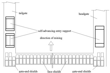
Figure 5: Roof support at longwall face and headgate and tailgate face-end outby T-junctions.
In the 7-m (23 ft) whole seam one slice longwall mining system, the development of the 7m (23 ft) high two-legged shields is the key to the successful operation of the system. Its design requires high-level reliability, stability and manufacturing know-how. It is equipped with a three-staged clipper covering 2/3 of the face height preventing severe face sloughage and hazards. The hydraulic legs are larger and longer; the state-of-the-art largest leg cylinders 500 mm in diameter are used so that it can provide maximum possible working resistance and with the maximum possible working height range, two stage telescopic legs are maintained for the working height. The welding technique is also important for the integrity of the structural components under the heavy-operating condition. The shields must maintain stability for seam undulation within 3-5˚.
The mines are operating on three shifts/day and seven days/week. Each day, the first two shifts are production shifts, and the third shift is for maintenance. The labor organization varies somewhat from mine to mine. An example is the production shift consists of 17 members: one foreman, two shearer operators, three shieldmen, one each of a headgate and tailgate man, two electricians, four outby repairmen and three cleaning men. The maintenance shift consists of 38 members. So the total daily production crew including management is 82.
For the rest of the 57-plus longwalls with whole seam one slice 6 m to 7 m (19.7-23 ft) cutting height, most employ Chinese-made face equipment.
Roof Supports
Entry support employs a combination of multiple systems. For the roof, it’s a combination of roof bolt + steel strap + wiremesh + cable bolt. For the ribs, the panel side is a combination of glass bolts + synthetic mesh + strap, while for the pillar side it is a combination of steel roof bolt + wiremesh + strap.
Figure 5 shows an example of the primary support of the headgate and tailgate. In the roof, resin bolts, 18 mm x 2.1 m (0.7in x 6.8 ft) are installed in 1 x 1 m (3.3 ft) or 1.3 x 1.3 m (4.2 ft) pattern. There are 4 bolts/row in the headgate and 6 bolts/row in the tailgate, supplemented by cable bolts, 17.8mm x 8m (0.7 in x 26 ft) with 1.5 m (4.9 ft) anchor length at 3 x 2.5 m (9.8 x 8.1 ft) pattern. The roofs are wire-meshed and frequently with straps. The rib bolts consists of four rows of tension bolts, 18 mm x 2.1m (0.7 in. x 6.9 ft) on the pillar side and three to four rows of fiber glass bolts on the panel side installed at 0.9 x 0.9 m (35.4 in.) or 1.3 x 1.3 m (4.2 ft) pattern. Fiber glass bolts are used in the panel side for convenience of shearer’s cutting. The tailgate primary supports are heavier than that of headgate because it is adjacent to the previous gob. Unlike the tailgates in the U.S. longwalls, no standing (supplementary) supports are used except at the T-junction area. Note the floor is paved with concrete slab about 200-mm (8 in.) thick in the headgate and 400-mm (16 in.) thick in the tailgate.
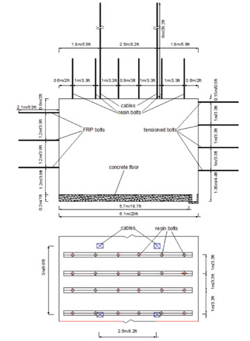 Figure 6a: Roof support at tailgate.
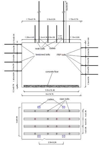 Figure 6b: Roof support at headgate.
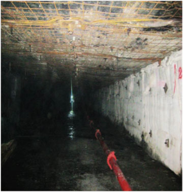 Figure 6c: Underground.
Figure 6 shows the supplementary supports installed out by the T-junctions of headgate and tailgate. They are self-advancing hydraulic supports for supporting the roof at the areas immediately out by the T-junctions. One set of self-advancing support is installed at the headgate and two sets in tandem are installed at the tailgate. The advance of the supports is as follows: the two sets in the tailgate have one double-acting (DA) ram on each side connected to each other. During advancing, the inby support is set against the roof and floor and it uses the DA ram to push the outby support forward. When the outby support has advanced to the preset distance, it is set against the roof and it then uses the DA ram to pull the inby support forward. The single set of support in the headgate is connected to the gate end shields at both sides of the stage loader. So its advance is concurrent with the stage loader. All three self-advancing hydraulic supports are elctrohydraulically controlled. The headgate set, 5.5-m long x 4.05-m wide x 3-m high (18×13.3×9.8 ft) provides a support density of 0.201 MPa (2.1 tons/ft2), while the tailgate sets, 5.03 m long x 2.84 m wide x 2.7 m high (16.5×9.3×8.9 ft), have a support density of 0.34 MPa (3.55 tons/ft2).
Summary
Through partnership among coal producers, equipment manufacturers, and research institutions, China developed the ultra-thick seam longwall mining system by stages: prior to 2005, development and application concentrated on 4.3- to 5.5-m (14.1-18 ft) thick seams; in 2007, the system applied to 6.3-m (20.7-ft) thick seams was introduced; and in 2009, the 7-m (23-ft) thick system went in operation. After more than three years of operation, it has proven that the system is reliable (See Figure 7) and has expanded to more than 60 longwalls (for the 6-m plus mining height) all over the country. China is now working on, and looking forward to, the introduction of the 8-m (26.2-ft) thick longwall mining system.
This research was sponsored by the Chinese Natural Science Foundation under project No.U1261207.
Author Information
Syd S. Peng is a professor from WVU’s Mining Engineering department, who specializes in deep mining. Huamin Li Ying Zhou are professors with Henan Polytechnic University, Henan, China, and Jingyi Cheng is a professor with China University of Mining & Technology, Xuzhou, China.


