
Superior Industries announced conveyor idlers with new bearing seal designs and a flush end disc that helps eliminate pinch and catch points. (Photo: Superior Industries)
In February, MSHA announced that, so far this year, three miners have been permanently injured when adjusting or cleaning conveyor rollers, pulleys and idlers while the belt is in motion. The injuries resulted from, among other things, trying to remove ice, mud or buildup from the belt, components, or pinch points. To prevent such injuries, MSHA advised to keep guards in place, follow procedures, and provide safety training.
Several solutions on the market are designed to reduce buildup or carryback, to reduce maintenance requirements and simplify maintenance tasks, to eliminate pinch or catch points, and to provide real-time data that can be used in preventative maintenance. And for almost every solution, topping the list of benefits offered is improved safety.
Major Redesign Nixes Catch Points
Superior Industries announced “the most significant redesign to conveyor idlers in decades.” The company said the new idlers exceed the company’s performance standards.
“We’re excited for conveyor owners and operators to benefit from this upgrade,” said Jason Adams, president.
The redesign includes two major innovations. The supplier’s idlers now feature a new weld that creates a flush end disc that prevents material from being trapped between the roll and idler frame. And new bearing seal designs “provide extended longevity for demanding applications,” the company said.
The flush end disc “eliminates a common pain point for customers by removing an exposed weld, which can cause premature roll failure,” said Riley Arndt, strategic account manager, Superior Industries.
“The exposed weld, usually between the end of the stand and the outside of the roll, can snag foreign material and cause the roll to seize up,” he said. A seize-up can “damage the seal and the idler,” or “slow down throughput and increase energy consumption.”
Pinch points and catch points are among “the main reasons for idler malfunction,” Arndt said. “It’s essential to keep your roll spinning freely and prevent any damage or pinch points” that lead to “downtime, lost production, and expenses.”
The new flush end disc offers no “point of attack for foreign materials,” he said. It “enables the end disc to sit flush on the idler roll.” The weld itself “is fully contained and cannot be damaged by the belt.”
The new weld design was subjected to lengthy testing that proved it could “work in all environments, from high-tonnage mining and quarrying to humid and arid markets, to coal production,” he said.
“The markets these idlers are going into will be tough and abrasive, but through the years of testing that we’ve done, the idler itself has performed better than the competition,” Arndt said. “The longer that idler and roll can run, the more you’ll be able to use your maintenance time elsewhere.”
The new weld design is complemented by new bearing designs that were driven in part by customer feedback. “In 2020, the company unveiled a series of upgraded bearing seals to help its conveyor idlers withstand the different elements its customers were facing,” Arndt said. “Four years on, it has partnered those changes with a new-designed idler.”
Depending on site specifications and the application, the new-designed idler can feature any of four specialty seals, the first of which were developed to help a customer solve an all-too-common problem. “The customer’s tunnel, which housed a conveyor, would not stop flooding,” he said. “This caused the belt to be underwater for a significant time.”
In response, Superior Industries developed and released “the SpinGuard Wet Seal for high-moisture environments with frequent washdowns and dredging,” Arndt said. “The SpinGuard Dry Seal is designed for environments with high dust concentration like coal,” he said. “And the Spin Guard Eco Seal is best for lower power consumption on long-distance, overland conveyors.”
Completing the series is the SpinGuard Titanium Seal, “considered the supplier’s top-draw seal,” he said.
“It is a combination of wet and dry seals for a premium design meant to significantly extend idler bearing life,” Arndt said. “It offers protection against any moisture or dust and fines that could penetrate the seal and cause them to fail quickly.”
The seal is ideal for applications at mine sites. “Some people call those applications extreme, but I see cases of moisture and dust affecting traditional idler performance at most producer sites I visit,” he said.
“The four types are built to help each operation have their choice to suit their situation best because not every conveyor is the same and not every application is the same,” Arndt said. “Our approach allows them to be application specific.”
The announcement follows a $4.5 million investment in production facilities that introduced more robotics in the manufacturing process for improved speed and accuracy, Superior Industries said. “The integration of robotic manufacturing ensures a level of consistency previously unseen.”

The Praetorian Conveyor Health Monitoring System, a fiber optic cable-based system that offers real-time reporting on idler condition, is installed. (Photo: Hawk Measurement)
Health Monitoring Drives Preventative Maintenance
Hawk Measurement said the Praetorian Conveyor Health Monitoring System (CHMS) can cut support critical decision-making by generating timely information on both an entire system and also the individual components of it.
“It is able to tell you the condition of your idlers every moment of every day in a simple traffic light system,” said Mathew Cook, product manager, fiber optic. “Each morning, after you pour your coffee and sit down at your emails, you have a report telling you which idlers need replacing now and which idlers will need replacing during the next shutdown.”
The system is comprised of fiber optic cables and a software system. “The system uses a pair of fiber optic cables mounted in a casing structure attached to the conveyor’s stringer,” Cook said. “The Praetorian System, living in a switching or control room nearby, is connected to these fibers.”
The system can detect abnormalities in the system and diagnose the cause. “Small changes in light caused by the vibration of each idler set can be interpreted by the onboard systems to be early stage faults occurring within the idler that may not be able to be detected by human senses,” he said. “The praetorian CHMS system can be connected to up to 10 km of conveyor belt per system and multiple belts can be connected together to see the entire conveyor system.”
By automatically monitoring the health of the conveyor, labor is reduced and unplanned downtime can be eliminated. “A praetorian CHMS system will reduce the amount of time spent inspecting idlers while increasing the accuracy of that inspection and while removing people from the line of fire,” Cook said.
Improved accuracy translates to the “risk of catastrophic idler failure being significantly reduced,” he said. It also translates to a “direct reduction in unplanned downtime by allowing the user to undertake guided, measured and accurate preventative maintenance of idlers during scheduled maintenance windows.”
By contributing to safety improvements, Praetorian CHMS can also help reduce other costs. “When using the optional CHMS Fire detection system it is possible to negotiate insurance premiums for operating conveyors,” Cook said.
The system’s history goes as far back as “a research grant in 2013 from Melbourne water for looking at fiber optic sensing for pipe leak detection,” he said. The research uncovered “the wide range of options and applications for a linear vibration sensor.”
In 2015, Hawk Measurement began researching “installing fibers on belts and working with some of our customers to undertake trials over the next few years,” he said. “Commercial launch of the conveyor product was in 2018 with adoption being relatively consistent.”
Since the launch, the company has invested in “improving the designs, processes, procedures and logistics that are required to successfully install large conveyor projects,” Cook said. “Our largest single installation is a 7-km network of conveyors in Australia on a large coal-fired power plant monitoring some 20,000 idlers,” he said. “The system was installed during the pandemic closures and has been running successfully ever since.”

The Return Training Bracket, a belt-training device offers a proven method of knocking/skewing idlers. (Image: PPI)
Bracket Knocks, Trains Idlers
Precision Pulley & Idler (PPI) released the Return Training Bracket (RTB), a belt-training device that effectively knocks idlers while using less labor.
“The RTB replaces an existing 4-1/2-in. drop bracket on a standard return idler,” said Mike Roozeboom, industry product manager. “The design of the RTB then allows an operator to steer return idler rolls to correct conveyor belt misalignment.”
The solution offers “a proven method of knocking/skewing idlers and making that process much easier,” Roozeboom said. “Knocking or skewing idlers is a fairly labor-intense process, where the operator would have to loosen bracket bolts and make slight adjustments, then start the conveyor belt back up again and see how the belt reacted,” he said, “and if it wasn’t right, they’d have to repeat the process of loosening and tightening multiple bolts until the correct belt path was achieved.”
In comparison, RTB uses “an easy locking handle that eliminates the need to loosen and tighten bracket bolts,” he said. It also “provides far more adjustment for the return roll than traditional drop brackets.”
The solution is cost effective and offers “a proven method to train a conveyor belt,” Roozeboom said. “It stands out from the competition because it is a patented product so there are proprietary concepts novel to PPI,” he said. “There are many belt training devices out in the market but we’ve really gone back to the methodology of keeping it simple.”
RTB can help prevent damage to conveyor framework. “The opportunity for spillage is minimized when the conveyor belt is aligned correctly,” Roozeboom said. “All operators know that when a conveyor belt is running properly it allows maintenance personnel to focus their efforts on a variety of proactive projects that help keep their plants running smoothly.”
A properly running belt is too often “taken for granted,” he said. “It allows attention and resources to be devoted to other priorities in the mining operation.”
RTB was in development for roughly a year. “It worked its way through our engineering group through a couple different iterations,” Roozeboom said. “We worked closely with different operators to develop a product that was based on their real-world feedback,” he said. “We may think we’ve developed the greatest product ever in a 3D modeling environment, but we needed the field trials and user feedback to help develop and refine the product to what it is today.”
During the many field trials, RTB was applied to a “problem belt, and experienced successful outcomes time and time again,” he said.
The solution will interchange with PPI standard CEMA B, C, & D return rolls with 4.5-in. drop brackets.
The Q1 launch “gives maintenance the opportunity to plan installations during these typical slower months of the year prior to the spring thaw when plants fire back up to full steam,” Roozeboom said. “Users have been seeking a simple, cost-effective solution to train their belts, and PPI has hit the mark with this product!”

Paul Byrne, managing director, Prok, cuts the ribbon on the new Salt Lake City facility. (Photo: Prok)
Wear-indicator Tech Cuts Costs
PROK opened a conveyor idler and roller manufacturing facility in Salt Lake City, Utah, in late January. It is the second new North American facility for the company and will help it keep up with market demand, the company said.
“PROK continues to invest in manufacturing capabilities aimed at making our customers successful,” said Tim O’Harran, vice president of sales, North America. “A core PROK business principle is to be local and useful,” he said. “Expanding our North American footprint allows us to work closer with our customers to deliver high-performance solutions.”
The facility will better equip the company to support and collaborate with customers. “PROK North America is comprised of engineering and tenured industry talent that routinely consults with mine engineers to implement our design principles,” O’Harran said.
“We reduce mining operations’ total cost of ownership by working closely with miners to ensure that our products and solutions not only achieve performance expectations but contribute to the mine’s profitability,” he said. “Working together is key to our mutual success and benefits mine operations because they lead the solution, while gaining technical introspect sure to maximize pay-dirt.”
PROK grows its business by helping customers solve specific, technical problems. “We complete our due diligence with on-site facetime with our clients, by making system observations and collecting facts,” O’Harran said. “PROK provides exact needs rather than guidance through a products catalog,” he said. “We initiate with a methodical approach that includes root-cause analysis and a solution-design process that places emphasis on a lucrative B2B relationship.”
PROK reported the new facility will “revolutionize the production” of its conveyor rollers, which are engineered for longevity and reliability. “PROK Rollers are designed for smooth rotation, low noise, long service life and operating economy,” O’Harran said.
“We only source high-quality materials to ensure that our products supply conveyor uptime,” he said. “Bearing, steel and composite material selection is critically important to quality assurance.”
The rollers provide vibration-free operation and can support future capacity increase. “Maximum performance is achieved by optimizing the roller-load capacities of shells, shell ends, and bearings,” he said. “Premium bearings and very effective labyrinth seals ensure that our rollers are built for tough underground mining conditions.”

Customized belt cleaners by Richwood Industries offer uninterrupted operations, minimized downtime, and (above) simplified maintenance. (Photo: Richwood Industries)
The rollers can be configured to “the conveyor design parameters and the mine itself, not guidelines,” O’Harran said. “With respect to a widely applied standard rating system, we use the bearing L10 life of a D & E CEMA-rated roller of 60,000 hours for our baseline calculations,” he said. “PROK rollers are designed to limit bearing deflections by selecting stepped-up shafts between the bearings and correct base-frame members to ensure a totally optimized design.”
Compared to competitor solutions, PROK rollers are easy to install, he said. “Our latest roller innovations include a lighter-weight roller” for easier handling. “In situations where a conveyor hasn’t been equipped with this latest technology, we offer a conveyor belt-lifting device to aid in the safe replacement of often heavy steel rollers.”
The new facility will also “manufacture PROK HDPE, a high-tech composite roller featuring groundbreaking visual wear-indicator technology, a world-first in the industry,” the company said. PROK HDPE offers “enhanced efficiency and cost-effectiveness for mining operations globally.”
The “lightweight, heavy-duty alternative to a steel roller offers the world’s only visual wear indicator, which provides miners the opportunity to become more predictive and less reactive,” O’Harran said. “Our two-toned co-extruded tube creates a visual indicator that identifies when a roller needs to be replaced, which simplifies maintenance activities.”
PROK innovations draw on a half century of experience in the area. “PROK is one of the world’s leading manufacturers of conveyor components,” O’Harran said. “Our conveyor rollers and pulleys go well beyond the conveyor products that have commoditized the mining industry.”
Belt Cleaner Minimizes Maintenance
Richwood Industries Inc. reported its customized belt cleaners deliver superior performance and reliability.
The solutions can be customized to the specifications of the site and application. “Through multi-point assessments of application factors such as belt speed, width, and material characteristics, Richwood delivers application-specific recommendations,” the supplier said in a prepared statement.
Top features include innovative designs. “Heavy-duty frames and industry-leading cleaner blade pressuring systems guarantee consistent blade-to-belt contact, even in heavy-duty or extreme conditions,” Richwood Industries said. The solutions offer full belt-width cleaning. “Richwood’s belt cleaners innovate with a single-blade system that ensures thorough cleaning without the drawbacks of segmented designs.”
Top benefits include improved efficiency and production, the company said. “The belt cleaner isn’t just a component,” said Scott Smith, research and development manager. “It’s a key factor in operational efficiency and safety in mining,” he said. “It impacts every facet of production, from safety to cost savings, making it an indispensable investment.”
An effective belt cleaner delivers a rapid return on investment by helping improve long-term sustainability and delivering cost savings, the supplier said. “A commitment to operational excellence, with the right use of technology and innovation, helps achieve productivity goals and allows for long-term sustainability,” Richwood Industries said. “Additional benefits are uninterrupted operations, minimized downtime, mitigation of wear and tear on components and minimized manual cleaning,” the company said. “All of these deliver substantial and identifiable cost savings over time.”
The belt cleaner requires minimal maintenance. Blade designs include dual-wear surfaces. “When the service life is completed on one side, simply flip the blade for a new cleaning surface,” Richwood Industries said.
Adoption and deployment of the solutions can contribute to worksite safety improvements and regulatory compliance. “Clean conveyors mitigate the risk of accidents and injuries, fostering a safer working environment and safeguarding personnel,” the supplier said. “Compliance with regulations minimizes the risk of fines and penalties associated with carryback housekeeping issues.”
The first-generation belt cleaners were released in 1987. “Continuous improvement followed, but the original quality has endured,” Richwood Industries said.
“Over the decades, the commitment to customer satisfaction has solidified Richwood’s position as a global leader in conveyor technology,” the company said. “As the industry continues to evolve, embracing innovations that optimize performance and mitigate risks remains imperative for mining applications around the world.”
Cutter Skiver Simplifies Belt Prep
Flexco reported the new Cutter Skiver, with capabilities of both the 900 Cutter and the FSK Skiver, will be released in Q2.
“It’ll cut and skive just about any belt a coal mine will throw at it,” said Kevin Fales, product manager.
The unit fills a critical niche and usage can add to belt longevity, he said. It is the right tool for the job. Currently, more often than not the job is done with the wrong tool.
“Today there are still too many knives used to prepare belts in the world of mining,” he said. “There are engineered solutions that make the process of cutting or preparing a belt safer but are often a series of tools.”
There is a tool for each step. “First, the technician must measure and mark a square line across the belt width. Then, the belt must be cut along this line,” Fales said. “After the cut, the best practice for mechanical splice and belt cleaner interface is to ensure the belt is skived with the proper reach-back and depth to recess the splice,” he said. “Today, these two steps, the cut and the skive, are often done with a knife.”
Less often, “engineered solutions are used, and they’re still frequently two separate tools, a belt cutter like the 900 Cutter and a belt skiver like the FSK Skiver,” he said. “The new Cutter Skiver takes the best from both tools and merges them into one piece of equipment.”
Use of the Cutter Skiver is safer than using a knife. “The less work a miner must do with a knife, the greater the safety, and lower the injury risk,” Fales said.
“The cutter blade is concealed in the body of the tool, eliminating exposure to a cutting risk,” he said. “Also, it’s fewer tools to move around to do the job when two tools are consolidated into one tool.”
The Cutter Skiver is intuitive to use. “The set-up is ergonomic, with updated knobs and the ability to use a ratchet driver or powered driver,” Fales said
Being easy to use and capable of multiple functions, its use saves time. “When using the tool, you no longer have to remove the cutter to do the skive,” he said.
“Once the belt is cut, you simply slide the tool or belt a few inches forward in the tool, and you’re now set-up to skive, which helps shave some time off belt preparation,” Fales said. “The addition of powered options also helps with time spent.”
The ergonomic design and intuitive use speeds up training and helps close a knowledge gap that impedes smooth operations. A trending “area for concern” in the industry “is the knowledge gap of the new hire verses the person they’re replacing,” he said.
“It’s critical to make the work processes clear, easy to follow, and, most importantly, safe,” Fales said. “The Cutter Skiver ensures the process of preparing a belt for mechanical fasteners is repeatable, consistent, and safe.”
Flexco offers training, and instructional videos are online.
The popularity of the rail-mounted skiver prompted the supplier to find “a way to adapt it for use with our 900 Series Belt Cutter so it could be used with all styles of mechanical fastener,” he said.
Prior to release, the Cutter Skiver was trialed by a coal miner in the Southeast that was reluctant to part with it when the time came. “During field testing, we wanted the units back for engineering and technical review to see if there’s any unusual wear and tear, and to check out how the components are holding up,” Fales said. “The field trial went so well that the customer asked if they could hold to them a little bit longer.”

Figure 1 (Image: Martin Engineering)
Calculating Belt Cleaner Placement on Coal Conveyors
By R. Todd Swinderman
For top performance, secondary belt cleaners must be properly placed and positioned. There are structural, spatial and safe-access considerations that can pose limitations on placement. Discharge-chute configuration and installation of a dribble chute to capture extra discharge may need to be factored into the design. This article will discuss design calculations for the location of secondary cleaners.
Placement and Positioning
The Conveyor Equipment Manufacturers Association (CEMA) defines the secondary position as the space between the head and snub pulley on the return run of the belt [Fig.1]. Unfortunately, structural designs often result in a very short section of belt surface between the head pulley and the snub pulley. This short distance allows little room for belt cleaners in the secondary position.
The challenge is further complicated by the need for space for a dribble chute. In addition, designers often locate work platforms based on major components. The platforms provide visibility and access for belt cleaner inspection or maintenance. Belt cleaners typically require more attention than major components to ensure system efficiency because the blades are wear components that must be maintained at optimal cleaning pressures.
Design And Installation Considerations
There are many simple options designers should consider:

Primary, secondary and tertiary cleaners are all specially engineered for purpose and placement. (Image: Martin Engineering)
1. Is the drive pulley wrap angle really needed?
A common default wrap is 210° created by the position of the snub pulley. The gap between the head pulley and snub is an ideal location for a secondary cleaner but the combination of pulley dia. and wrap angle may make mounting a secondary cleaner difficult and maintenance nearly impossible. Operators should use an updated engineering design program that employs either the DIN or CEMA methods for the calculation of accurate tension values and the required wrap angle, ϴ.
2. Consider using a larger-dia. head pulley.
Choosing a head pulley based on the minimum dia. may seem like it saves money; however, MSHA reports that up to 85% of maintenance problems are due to fugitive materials, which increase costs for cleanup, labor, and equipment replacement.1 A larger head pulley can allow the installation of two cleaners in the primary position and enough snub-pulley space for one or two cleaners in the secondary position, significantly reducing the amount of fugitive material.
3. Prioritize access to the belt cleaners.
Maintenance personnel can spend up to a third of their time merely gaining access to the equipment. Designing access to seldom-inspected or -maintained components based on minimum walkway codes raises costs. Consider structure and work platforms that allow belt cleaner inspection and maintenance.
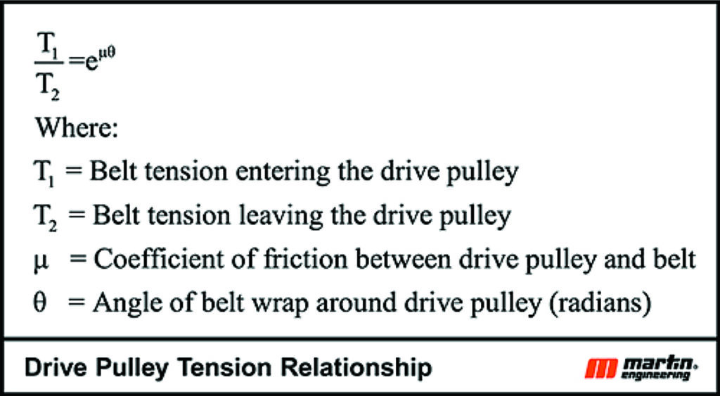
Figure 2 (Table: Martin Engineering)
4. Consider using motorized-drive pulleys.
Motorized pulleys offer energy advantages and weight savings and open up space for belt-cleaner installation and maintenance. Since all rotating components (including the main bearings) are located inside the pulley, the external stub shafts need minimal space to be mounted to the structure.
5. Consider professionally trained installation.
Belt cleaners must be mounted properly, often to within ± a few millimeters, to perform optimally and limit the possibility of damaging the belt. Contracting with the belt cleaner supplier ensures proper installation with minimal adjustment and that the new chute will retain a clean, professional look.
Calculating The Adequate Belt Tension
A critical design requirement is to determine the amount of wrap-around the drive pulley requires to provide the adequate conversion of torque from the drive into belt tension sufficient to move the belt without slipping. It is interesting to note that the fundamental relationship describing this transfer does not depend upon the pulley dia., only the coefficient of friction, µ, between the belt and pulley and the wrap angle, ϴ, and the belt tensions required to prevent slip [Fig. 2].
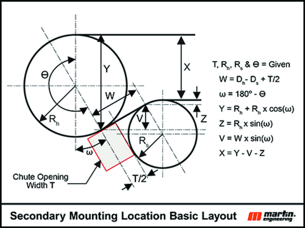
Figure 3 (Image: Martin Engineering)
Secondary Belt Cleaner Location Geometry
Assumption: Top and bottom runs of the conveyor belt (X) are parallel entering the head pulley and leaving the snub pulley [Fig. 3].
Variables:
ϴ = Wrap angle of belt around head pulley.
ω = Wrap Angle, ϴ, – 180°.
H = The height of the opening for the secondary belt-cleaner
blades and frame installation.
Rh = Radius of the head pulley plus lagging, plus belt thickness
Rs = Radius of the snub pulley plus lagging, plus belt thickness. (Snub pulley dia. default value: 0.64 × the head pulley dia., per DIN 22101.)
T = The width off the opening for the secondary belt cleaner blades and frame installation.
W = Length of belt segment tangent to both the head and snub pulleys.
X = Distance between top and bottom runs of the conveyor belt.
Y = The vertical distance between the top run of the conveyor belt on the head pulley and the tangent point where the belt leaves the head pulley and starts the return run.
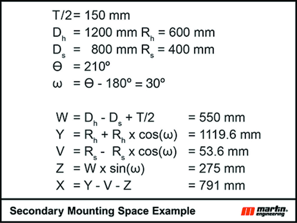
Figure 4 (Table: Martin Engineering)
Some secondary cleaners must be mounted at least 50 mm from the point the belt leaves the head pulley. This offset also needs to be considered. In addition, the X dimension should be checked with the idler dimensions for adequate installation space [Fig. 4].
A similar analysis for the location of pre-cleaners shows that with a 1,200-mm-dia. head pulley, two primary cleaners can be installed in addition to a secondary cleaner. The addition of tertiary cleaners would be possible but may not be necessary if two pre-cleaners and a secondary are mounted on the head pulley.
A belt-cleaner system should be properly specified, designed and installed to gain the direct and indirect long-term cost-benefits of reduced fugitive material, but compliance is an issue as well. OSHA, 1926.1412(d)(1) and MSHA 75.362 state, “a competent person must begin a visual inspection prior to each shift the equipment will be used, which must be completed before or during that shift.”2 Safe access with adequate space for maintenance and inspection is critical to supporting longer system life and a lower cost of operation.
References
1 2014 Pit and Quarry Operations Handbook, Chapter 10, page 145.
2 Occupational Safety and Health Administration (OSHA), “§ 1926.1412 Inspections”, Dec, 2023. www.ecfr.gov/current/title-29/subtitle-B/chapter-XVII/part-1926/subpart-CC/section-1926.1412.
R. Todd Swinderman is P.E., president emeritus of Martin Engineering and former president of CEMA.

