

Mistracking can happen quickly and lead to excessive downtime to remedy.
Training operators and maintenance personnel in techniques to reduce mistracking is an effective way to mitigate mistracking issues
By R. Todd Swinderman
With so many factors contributing to belt mistracking, achieving perfectly centered alignment may not be possible for most conveyor systems. Everything from ambient temperature to changes in material grade can impact belt alignment causing spillage and belt damage. But mistracking is as much a safety issue as it is an efficiency and spillage issue, so monitoring belt drift to avoid contact with the structure is critical.
The U.S. Mining Safety and Health Administration (MSHA) attributes approximately 30% of belt fires to friction caused by critical mistracking or belt slippage.1 At the point of a fire, the tell-tale signs of mistracking — material spillage, belt and structural damage — were likely already occurring. When these signs are noticed, immediate tracking remediation is required before returning the system to production. Causes of misalignment must be reviewed and addressed otherwise it may result in permanent belt damage or even structural collapse. Temporary fixes for mistracking are often employed but, for safety and long-term economic reasons, a permanent solution should involve a modern tracking system.
Operators need to know when misalignment becomes actionable and what to do about it. A new document by the Conveyor Equipment Manufacturers Association, titled CEMA’s System Mistracking Allowance Guide 20232, provides a comprehensive guide to identifying when the belt has drifted from normal operating tolerances into a serious workplace hazard. This article will discuss the newly released CEMA Guide as it provides additional direction on actionable and critical mistracking.
Current CEMA/ISO Standards
CEMA’s Guide and the International Organization for Standardization (ISO) Standards 14890 and 15236-1 are very similar in their recommendations for normal belt deviation from the central path. The CEMA Guide is based on standard CEMA components and the ISO standards on the conveyor belt construction tolerances such as camber and troughability.
According to the ISO allowance, the conveyor belting, when running on a correctly aligned conveyor with centered loading, should not deviate from the central track by more than ±40 mm (±1.5 in.) for a belt width ≤ 800 mm
(≤ 31.5 in.), or by more than ±5% of the belt width for widths > 800 mm with
a maximum of ±75 mm (±3 in.).
Attempt to control critical mistracking symptoms using a timber.
Allowable, Actionable and Critical Mistracking
Allowable Mistracking is the amount of design mistracking under normal conditions. Some deviation from perfect tracking is bound to happen on any system due to many operational and environmental factors. The CEMA allowable tolerance was established for normal running conditions.
Actionable Mistracking happens when operational or environmental factors influence belt tracking to the point where spillage or damage to the belt and/or structure occurs. Best in class operators will plan action to correct this level of mistracking as soon as practical.
Critical Mistracking is a second-level fault that creates an immediate and serious risk of substantial damage and injury to personnel. Critical Mistracking must be corrected immediately to avoid additional spillage, belt or structural damage and other safety incidents.
System Requirements for Mistracking Allowance
Consistent belt tracking is a system issue that must be addressed at every stage from specifications to the conveyor’s initial design, installation, operation and maintenance. The project specification should state the mistracking allowance as it affects the selection of the belting, structural clearances and rotating components.
Belt quality – The belting should be new and sourced from a manufacturer of high-quality equipment. Used belting will have wear, tear, and stretching from its previous system. Low-quality belting may not be manufactured to Rubber Products Manufacturers Association or ISO requirements. Incorrectly specified belting might not trough properly resulting in poor contact with the idlers.
Belt width – The width of the belt selected should be based on 85% of the CEMA standard cross-sectional loading to allow for variations in loading and adequate free belt edge so the belt does not run out from under the sealing system.
Idler allowances – The CEMA mistracking allowances are based on standard CEMA idlers. Consideration should be given to using offset return idler brackets because the return run is lower in tension and therefore the idlers have less effect on maintaining a center track and greater mistracking is possible.
Pulley allowances – The main pulleys should be selected so the belt doesn’t run off the pulley face. This may mean specifying a wider pulley face than a standard CEMA pulley.
Structural allowances – The structure should allow a free path for the belt including the mistracking allowances.
Fig. 1 – CEMA Carry Side Mistracking Allowances.
Conveyor Installation and Retrofits
Installation of the conveyor structure and alignment of the rotating components is the foundation of a system designed to track properly. Often when replacing a belt, components are moved out of the way and not reset in the proper position. Mixing idler brands to save a few dollars or in search of the “perfect” idler can affect belt-to-idler contact and loading point spillage.
CEMA installation tolerances should be followed in the fabrication, erection and mounting of the rotating components. Benchmarks should be established, especially for the main pulleys, so in the event of chronic mistracking, there is a reference for confirming the main pulleys are level and square as a starting point for correcting mistracking.
The same is true for resetting the idlers square to the centerline as they are often haphazardly knocked and shimmed in an attempt to treat symptoms rather than root causes of mistracking. There is a long-standing belief that the belt always tracks to the side of the idler or pulley that it contacts first, so many operators will adjust an idler by pivoting it slightly to move the belt tavel as a corrective action. However, when rolling components are misaligned both horizontally and from level, common corrective actions do not always apply.
When the components are misaligned both horizontally and vertically, the belt tries to flex and contact the component at both edges at the same time. Depending on the direction of travel, a out of level component creates a right hand (RH) or left hand (LH) screw thread effect and the belt may not respond intuitively depending upon which misalignment force dominates, making troubleshooting difficult.
Over time, several corrective actions along a system might cause the belt to develop a memory, making aligning a replacement belt difficult. Excessive adjustments of idlers to treat mistracking symptoms increases power consumption and bottom cover wear. When installing a new belt, it is best practice to reset the components within alignment tolerances.
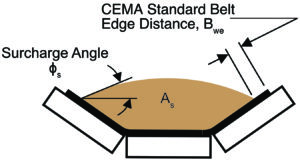
Fig. 2 – CEMA 100% Full Design Loading.
CEMA Misalignment Guidelines
ISO provides an overall allowance independent of the conveyor section or components. CEMA members realized that there was more to the question of misalignment than the free belt edge in the load zone and developed mistracking guidelines based on CEMA standard components. CEMA establishes mistracking allowances at three critical locations of the conveyors: main pulleys, the carrying side and return runs.
The CEMA guidelines vary from the ISO standards for 36-, 42-, 48-, 54- and 60-in. belt widths because the ISO allowances exceed the CEMA standard pulley face widths and for 54-, 60-, and 72-in. belt widths because the ISO Standards exceed CEMA manufacturers’ standard return idler brackets widths. These variances are easily overcome at the design stage by specifying wider pulley faces, offset return drop brackets and providing the required structural clearances.
Fig. 3 – CEMA Return Side Mistracking Allowances.
Carrying Side Mistracking Allowance
Carry side mistracking is usually not constrained by the idler roll length or load zone structural supports but rather by the possibility of spillage. [Fig. 1]
CEMA specifies a standard belt edge (Bwe = 0.055 x Belt Width + 0.9 in) designed to prevent spillage due to belt sag between carrying idlers outside the load zone when the belt is centrally loaded. [Fig. 2]
CEMA standard 100% full area, As, is based on the idler geometry, the standard belt edge, Bwe, and the surcharge angle. The standard area times the belt speed and bulk density give the CEMA standard capacity, Q. CEMA best practice is to design for 85% of the theoretical 100% full loading to accommodate surge loading and changing bulk material properties.
Return Side Mistracking Allowance
Return side mistracking is limited by the width of the CEMA 502 standard return rollers. [Fig. 3] Usually, the structure for mounting the return rollers is based on the carry idler base dimensions. The standard mounting brackets for return rollers are very close to the ends of the rollers in most designs. If the belt travels into the return bracket it can quickly be cut in two by the friction of the belt edge which is often embedded with fines and acts like a hacksaw blade. Serious injuries have resulted from failed brackets causing falling return idlers. Offset brackets are available but are really just treating the symptoms of mistracking rather than the root causes. Wide base carrying idlers can be specified which in turn would require using a return roll of the next wider belt side but this comes at an additional capital cost.
Fig 4. – CEMA Pulley Mistracking Allowances.
Main Pulley Mistracking Allowances
CEMA pulley misalignment tolerances are based on ANSI/CEMA B105.1 standard pulley face widths. [Fig. 4] When greater tracking variance is required, engineered pulleys are an option.
Proper Belt Loading
Operators and maintenance personnel should be trained on how overloading and off-center loading affects mistracking. Belt tracking is primarily through gravity (center loading) and friction (a minimum of 50% belt contact with the idlers). Spillage and carryback must be controlled for consistent tracking as buildup on idlers and pulleys changes the geometry of rolling components and can reduce belt-to-idler friction.
Fig. 5 – Determining conveyor skirtboard width based on mistracking and sealing system allowances.
Skirting and Mistracking Allowances
The CEMA Guide started as a best practice for skirtboard sealing systems because spillage in the load zone due to mistracking is a common problem. There are many different sealing systems on the market. Depending on the spacing of the skirtboards and the thickness of the sealing system, there could be differences in the amount of free belt edge needed in the design for Allowable Mistracking in the load zone. [Fig. 5] If there is a history of Actionable or Critical Mistracking that cannot be mitigated, then an even wider free belt edge is warranted.
Modern skirting designs are engineered to minimize spillage by creating a sealed environment within the loading zone. Depending on the type and allowable space of the belt, they can have a double seal that rides the belt offering greater sealing, but that can take up extra space on the belt edge. Skirtboards can lower maintenance costs by self-adjusting as they wear rather than having to be unbolted and adjusted manually when spillage becomes an issue. Once they have worn on one end, some models can be flipped to extend the equipment life.
Belt Training
Accessories to deal with mistracking may come standard with conveyor systems. These are often “brute force” trainers that prevent the belt from coming in contact with the structure and are not actually training systems but merely protective barriers that lead to system issues and belt wear. When the belt drifts, the brute force trainers can cause the belt to fold into itself and fold back into the system. This can permanently damage the belt and lead to further mistracking and spillage.
Brute force tracking devices treat symptoms rather than root causes of mistracking and often result in belt edge damage.
Modern belt trainers use sensing arms to detect slight variations in the belt path. These arms are attached to a pivoting idler that reacts immediately to these variations and trains the belt back into alignment. If detected early enough, less force is needed to retrain the belt and ensure alignment throughout the belt path.
Return trainers act in a very similar fashion but without a troughed roller. Training idlers are set slightly above the belt plane allowing the weight of the belt to offer some additional tension on the roller. As the sensing arm detects the belt drift, it turns the roller in the opposing direction to train the back into alignment. Since the low tension belt return can easily become misaligned, a return tracker is especially effective when placed near the tail pulley to ensure the belt enters the loading zone aligned.
Design Options
The CEMA Allowable mistracking recommendations are for properly loaded, unloaded, cleaned, maintained, and operated conventional troughed conveyors. The recommendations do not apply to horizontal curves or specialty belts such as side wall belts. A good starting point for designing for mislaignment is to examine current operating and maintenance practices either on your site or in your industry.
Conveyors bought on 100% loading and price alone often experience tracking issues. Knowledgeable conveyor designers should consult the owner on the significance of design allowances, the costs and benefits associated with wider belts and less than 100% loading best practices. Training operators and maintenance personnel in techniques to reduce mistracking is an effective way to mitigate mistracking issues.
The roller arms ride the edges of the belt moving with horizontal variations off of the center line.
Laser alignment of components to CEMA installation standards is now a common technique for establishing conveyor alignment benchmarks. Positioning training idlers at critical locations is specified but commonly have limited ability to change the path of the belt when maintenance practices are poor, there are extreme environmental conditions or buildup on the rolling components.
Over the life of a conveyor, it is cost-effective to contact CEMA member companies for assistance in designing conveyors, specifying components, training or troubleshooting conveyor belt tracking issues. If there are no project or site-specific requirements, the recommendations in the CEMA’s Mistracking Allowance Guide provide reasonable assumptions for a conveyor designed and operated according to CEMA design guides and standards. The complete CEMA System Mistracking Guide is available from CEMA’s website: cemanet.org.
References
1 U.S. Bureau Of Mines Information Circular/1995 Analysis of Underground Coal Mine Fire Incidents in the United States From 1978 Through 1992.
2 Staff, CEMA’s System Mistracking Allowance Guide 2023, Conveyor Equipment Manufacturers Association, Inc. (CEMA), Bonita Springs, FL. www.cemanet.org.
Todd Swinderman, P.E. is president emeritus for Martin Engineering. He has authored dozens of articles and papers, presented at conferences and customer facilities around the world and holds more than 140 active patents.


