By Jack D. Trackemas and Syd Peng
Longwall mining is the preferred method in coal mining to maximize production and reserve recovery by extracting large blocks of coal that have been outlined with a set of continuous miner development entries. In the U.S., technological advances and system enhancements have steadily improved productivity more in the longwall retreat process as compared to the improvements in the continuous miner gateroad development process. Consequently, longwall extraction rates have outpaced gateroad development mining advancement.
Figure 1: Measurement data from loading of armored face conveyor.
Assumptions include full 42-in. web; 7.5-ft cutting height; bank coal density 93.7 lb/ft3; loose density broken 63 lb/ft3; V max < 3,500 tph of AFC; minimum allowable chain S.F. 1.5; motor breakdown torque of 2.4; friction factors are 0.38/0.3/0.4; conveyor width 1,142 mm.
This article addresses the factors considered for increasing panel width and the solutions to the technical concerns for increasing the longwall face width from the current accepted industry standard of 1,050 ft to 1,600 ft. The process of increasing the width of longwall panels, while helping to increase coal production, reducing continuous miner development, and increasing coal reserve recovery, will result in additional design considerations for equipment, roof control, ventilation design, infrastructure and longwall moves.
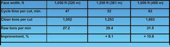
Table 1—Productivity Improvements
Note: Assumptions include: full web (42 in.); shearer at 35 fpm; shearer at 10 fpm in cut outs; material in place 93.7 lb/ft3; and 12 minutes for wedge cut 1.
Over the past several decades, coal companies have installed newly designed longwall equipment and increased longwall face productivity at coal mining operations. With the newly designed equipment, most major coal companies have strategically increased the width and length of longwall panels to reduce the amount of continuous miner development required to keep pace with the increased longwall retreat productivities. By increasing the width of a longwall face, the following benefits can be realized:• Improved longwall productivity since less time is spent in the wedge cuts at each gate end of the faces; consequently, a higher percentage of the time is spent mining coal from the middle of the face;• Reduction of higher cost gateroad development and the ability to maintain float time;• Improved reserve recovery due to the increase in longwall mining panel width and reduction in gateroad development mining in reserve blocks;• Reduced construction work associated with mining; and• Delayed timing of capital for subsequent face replacement.
Table 2—AFC Design Calculation
Note: H = headgate, T = tailgate; volume capacity of the AFC is approx. 2,500 tph.
The productivity of the longwall with wider faces improves because a higher percentage of time is spent mining, and a reduced amount of time is spent in the wedge cuts at each gate end of the face. Table 1 illustrates the expected productivity increase of the longwall for the different face widths.
Figure 2: Flow demand for pressures calculations.
Note: Maximum shearer speed of 60 fpm based on V max < 3,500 tph of AFC; Two shields will be movedin cascaded automation.
From the base case face width of 1,050 ft, the initial approximate 19% increase in width to 1,250 ft will result in an 8.1% increase in productivity, thereby decreasing the retreat rate of the face by 10%. The increase in face width by 52% to 1,600 ft leads to a 15.8% productivity improvement and a 24% decrease in longwall retreat rate. Multiple time studies were completed to determine the assumptions depicted in Table 1. The type of cutting used is bi-directional, meaning a taper cut is completed at the headgate and then a full web cut is completed and cut into the tailgate. The process is then reversed, and a taper cut is completed at the tailgate and a full web cut is mined and cut into the headgate.
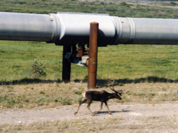 Figure 3: Hydraulic schematic of 1,050-ft wide longwall base case.
During this cutting process, the average shearer cutting speed for full web cuts across the face was determined to be 35 ft per minute (fpm) with peak tram speed of 45 fpm from headgate to tailgate passes and 55 fpm on tailgate to headgate passes. The main restriction of headgate to tailgate passes occurs due to the area available under the shearer.
In addition to the productivity gain, one of the most significant benefits of wider faces is the reduction of higher cost gateroad development with continuous miners. Based on a reserve district that measures about 10,700 ft by 7,700 ft, it will require either six 1,050-ft panels, five 1,250-ft wide panels, or only four 1,600-ft panels. Increasing the face width to 1,250 ft, about 19%, would reduce approximately 14.9% development footage, and increasing the face width to 1,600 ft, about 52%, would save 35.4% in development footage.
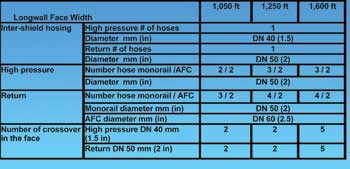
Table 3—Details of the Hydraulic System Hosing
The reserve recovery would improve by increasing the face width to 1,250 ft, by 353,723 tons or approximately 1.8%, and increasing the face width to 1,600 ft, would improve reserve recovery by 689,293 tons or 3.5%.
The construction work associated with development and retreat is also reduced. This reduced construction work for development saves time and expenses, including the cutting of overcasts, building of ventilation controls, installation of a belt system, installation of a section power circuit, and track installation. The construction work associated with the slower longwall retreat also saves time and expenses related to belt removal, power moves, track recovery, tailgate and headgate support, and reduced longwall moves.
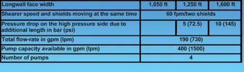
Table 4—Pressure Loss Calculations for Increased Face Length
Note: Shearer speed of 60 fpm and two shields moving at the same time.
The initial capital expenditures for widening a longwall face would increase; however, the total capital spending in the long term is similar because the wider panels retreat at a slower pace resulting in fewer shield cycles per reserve area. The shield cycle is the number of times the shield advances during the mining of the panels. For bi-directional cutting, the distance the shield advances during its cycle is governed by the cutting or web depth, which in this case is 42 in. The reduced number of shield cycles per reserve area allows subsequent capital purchases to be delayed. The typical cycle life of a properly designed shield is 50,000 cycles.
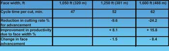
Table 5—Change in Face Advancement
From a cost and operating prospective, due to the additional clean tons mined, reduction in development cost, and reduced construction cost, the extension of panel width creates additional economic benefits relative to operating cost.
Base Case Description
The panel width of the base case was 1,050 ft. The mining units consisted of three continuous miner sections and the longwall. The coal seam, dipping toward southeast 0%-3%, was 6- to 8-ft thick and 500- to 800-ft deep, with some occasional overburden peaks of 1,050 ft. Methane liberation at the mine was considered moderate to high with a gas content of 180 to 250 ft3/ton. The immediate roof of the mine consisted of interbedded shale and rider coals. The main roof consisted of layers of sandy shale and interbedded with layers of limestone. Caving of the roof behind the longwall face has not presented any issues with shield loading. The immediate floor consists of shale and claystone, when exposed to water, can present some soft floor issues.
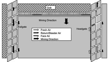
Figure 4: Typical longwall face ventilation currently used during the study.
The typical panel size mined was 1,050 ft wide and 10,000 ft long. Gateroad development was three entry, two chain pillar configuration and overall width of 200 ft center to center of outside entries.
The face shield supports were 2-m, two-leg shields with a support capacity rating during normal set pressure of 790 tons, and a maximum support capacity at yield of 1,096 tons. The mine used a total of eight gate end shields, four each at tailgate and headgate. All of the shields were electrohydraulic controlled. The current shield cycle time was 8 seconds.
The armored face conveyor (AFC) was rated at 3,500 tons per hour (tph) with a width of 1,142 mm. The AFC was powered by three 1,250-hp motors. Two of the motors were located at the head drive and the third motor was located at the tail drive. The three AFC motors were controlled by the use of Control Start Transmissions (CSTs). The speed of the conveyor at normal operation was 353 fpm. The AFC was equipped with a 42-mm twin inboard chain strand.
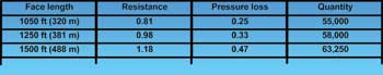
Table 6—Face Ventilation Resistance and Quantity Requirements
The stageloader was 1,532 mm wide, equipped with a 38-mm chain operating at 416 fpm, and driven by a 350-hp motor. The stage loader was also equipped with a top mounted crusher driven by a 400-hp motor.
The shearer was a dual drum ranging arm model. The hydraulic pumping system consisted of four pumps rated for 100 gallons per minute (gpm) with a 500-gallon reservoir tank designed for an operating pressure of 5,000 psi.
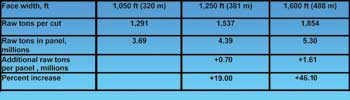
Table 7—Increase in Production (Raw Tons)
Note: Panel length is 10,000 ft, mining height in 7.5 ft and bank density is 93.7 lb/ft3.
The electrical system for the longwall used two power centers. The first power center was 3,400 KVA and controls the hydraulic pump system, 120 volt control circuits, and both master controls at the headgate. The master controls at the headgate maintained power to lighting, shield electrical hydraulics, methane sensors, and other control circuits. The second power center was a 7,000-KVA power center with a primary voltage of 4,160 volts and powered the face equipment including the face conveyor drives, the shear, the stageloader, mobile tailpiece, etc.
Design Factors for Increasing Panel Width
The major factors to review for increasing the panel width are the AFC, hydraulic system, electrical system, ground control, ventilation and degasification, and mine and system infrastructure. One of the biggest equipment considerations is the design of the AFC. The horsepower requirements on the wider face would push the limits of the newest technology. To calculate the requirements for the AFC, the following information was gathered and used for calculations. The volume capacity of the current 1,142-mm conveyor pan is 3,500 tph. The shearing machine speed was kept constant at 55 fpm from the headgate to the tailgate and 42 fpm from the tailgate to the headgate for horsepower and AFC loading. The constant speed of the shearer would be the worst case assumption.
Typically when mining across the face there are minor delays for face adjustments, conditions, etc. After multiple time studies, the average shearer speed for production purposes was more in the range of 35 to 36 fpm. The speed of the AFC for a 42-mm chain was specified by the manufacturer to be 353 fpm, and the speed of the AFC for the 48-mm chain was specified by the manufacturer to be 370 fpm. The difference in chain speed is a result of the sprocket design relating back to the geometry of the number of teeth required. The depth of cut (or web) created by the shearer was 42 in. The cutting height of the seam was 7.5 ft, with an in-place density of 93.7 lb/ft3 and a broke/loose density of 63 lb/ft3. The minimum allowable design chain safety factor recommended by the manufacturer was 1.5.
The use of the correct friction factors is important for all face conveyor calculations; however, the friction factors become more critical on wider faces. To obtain accurate friction factors, an AFC was extensively monitored over a period of time. Through a process of measurements, historical experience, back calculations, and based on the current horsepower on existing faces, representative friction factors were determined. After gathering this information and reviewing observations from existing systems that perform well, some of the key factors from calculations are displayed in Table 2 for the three different face widths.
The 1,650 hp requirements made it necessary to investigate fluid couplings, CST, and variable frequency drives (VFD) to minimize risk and increase reliability and performance. After reviewing the initial design of the fluid coupling option, the drive design was eliminated because the size of the unit was prohibitive. Most of the modern wider faces use the CST 45 series gearbox with 4,160 volt AFC motors and control programming during startup and operating. The 1,600-ft face requires a CST 65 series gearbox. The VFD and the CST options would provide soft startup, load sharing, overload protection and creep speeds. The VFD also could dampen the chain vibration. The VFD motor was not yet available in the 1,650-hp range at the time of this review, and the VFD system has not been proven reliable in this class.
Considerations for VFD also had to be given for the total harmonic distortion and the impact to the cables, ground faults, data transmission and communication system. The VFD would permit smaller sized units, an advantage for tip-to-face distances. The best feature of the VFD is that AFC chain speed can be varied. Currently, this is not a benefit in most mines in the United States because belt haulage systems are usually designed with excess capacity. Due to familiarity and experience with the CSTs, the decision was made to use CSTs for the wider faces.
Based on the results of Table 2, initial concerns arose about the amount of reserve capacity horsepower (10%) for the headgate to tailgate pass during mining for the 1,600-ft face width. The use of high strength steel in a 42-mm chain was discussed with chain manufacturers to provide the same strength as the 48-mm chain. The use of the 42-mm high strength chain links will reduce the weight of the chain by 30%, which would reduce the horsepower requirements. The new 42-mm chain had not been used anywhere and was not proven technology and concern was raised about its reliability. The use of the 48-mm chain appeared to be the best solution. The wear and reliability of the 48-mm chain appeared to be adequate for the wider face, as some mines in the coal industry were already using the chain with success. After discussions with these mines, concerns with handling of the heavier chain during moves for installation and maintenance for wear and connector links, the concerns were resolved.
The issue of reserve capacity horsepower still needed further review. A study was scheduled to measure the loading of the AFC for a “high production day” (approximately 10,000 raw tons mined per shift) was monitored to evaluate the concerns for reserve capacity horsepower for the headgate to tailgate pass during mining for the 1,600-ft face width. Figure 1 shows the results of loading of the AFC for three 8-hr production shifts with workers changing out at the face. The data was gathered by measuring the AFC motor currents.
The face width monitored was a 1,250-ft wide panel with three 1,250-hp motors using CST technology, 42-mm chain, and 1,142-mm wide AFC. The graph shows that rarely is the conveyor loaded more than 76% of the rated capacity in load during operation. The most frequent occurrence of loading occurs at 18% of the rated capacity in load about 11% of the time. The calculations in Table 2 were based on the conveyor being fully loaded, with the information developed in Figure 1, the issue of reserve capacity horsepower for the headgate to tailgate pass during mining for the 1,600-ft face width is minimal. Another method to mitigate the reserve capacity horsepower concern, if necessary, is to limit the speed of the shearer electronically as the shearer travels toward the tailgate.