
By Chuck Renner
Full stream mechanical coal sampling is the method used to collect samples to be analyzed for shipment quality in most cases. From these samples quality adjustments specified in coal supply agreements between coal companies and buyers can be made. If a sample is not collected according to ASTM methodology, accepted practices and proper manufacturer recommended maintenance of sampling equipment, there is no chance to obtain a correct laboratory analysis.
The basic unit of ASTM sample collection is the increment. Each increment (operation of the sampling cutter) is collected using guidelines recommended in the ASTM D7430–Standard Practice for Mechanical Sampling of Coal. This practice was first published in 2008. The purpose of this practice being published was to consolidate mechanical sampling guidelines and therefore provide one place in ASTM where information specific to mechanical sampling can be found. Coal supply agreements should reference this method for correct operation of mechanical samplers, auger samplers, total quality management of sampling systems and bias testing.
The sequence of events to obtain a contractual analysis sample is as follows:
- Loading: origin or destination sample collection;
- Primary sampler: collection of the gross sample—each increment weighs from 30 lb to 1 ton;
- Within system sample preparation begins: crusher—reduction of topsize;
- Preparation continues: secondary sampler—division of sample mass;
- Tertiary sampler: final sample;
- Handling of final system sample: transfer to other container, subjecting the sample to possible sample loss and unaccounted for moisture loss or gain;
- Division of sample: riffling;
- Air drying of sample;
- Division of the air dried sample: riffling;
- Pulverizing to obtain the 60 mesh analysis sample;
- Riffling and bottling for analysis;
- Multiple units of analytical equipment:
1 gram per 10,000 tons (or more); and - Human input and reporting to database.
Each step in this process is important. Multiple units of sampling, sample preparation and laboratory analysis are used. Several persons contact the sample from removal from the sampling system, sample handling, processing and analysis to go from 10,000 tons of coal (or more) to 1 gram (1/28 of an ounce) for analysis. A thorough quality assurance plan and audit plan must be in place to ensure that the process outlined above, going from 10,000 tons (or more) to 1 gram for analysis, is conducted correctly. It is also very important that the procedures are understood by site personnel to ensure consistent operation and sample handling. Training is needed on a regular basis.
Mechanical Sampling
Some have characterized the modern sampling system as “automatic” sampling, particularly with the use of programmable logic controllers used to control the system operating parameters. Personnel who are charged with the task of maintenance of a sampling system understand that the systems are mechanical devices and require routine preventive maintenance (PM). To ensure that the system availability is as close to 100% as possible, a proactive PM program is observed in systems operated by the most successful sampling system owners. Both the sampling system manufacturer and a testing company should be involved in the operation and correct maintenance of a sampling system. Hopefully the system owner will contact these professionals when issues arise instead of taking action that is not appropriate.
Operators of sampling systems who don’t have a comprehensive operating and maintenance program risk bias, availability issues and failure of audits by inspectors, which can show that the contractual sample is not taken correctly. When observers see issues it calls attention to the system operation and results in more frequent and detailed inspection and audit evaluation.
Table 1: Example Calculation of Cost Negative Moisture
Financial Consequences of Bias—Contract Issues
What is the financial consequence of a finding of bias? The table above shows that an unresolved moisture bias can mean significant financial liability. The contractual sampling system was tested for bias. The bias test resulted in a 0.19% moisture bias which was not subsequently resolved. When the bias test results were given to the utility, a determination of a financial liability was calculated and submitted to the coal company for reimbursement over the 1 million ton contract (See Table 1)
In the other case, in Table 1, the statistical estimate of moisture bias was 1%. In the case of a 1% moisture bias, the economic consequence was much larger for a contract that had nearly 5 million tons committed.
An additional consequence for the utility is that the opportunity for suspension or rejection may not be possible if the observed analysis and contract specification are borderline. One possible resolution for a bias is to just add or subtract as appropriate the estimate of bias to the contract specification. The flaw with that option is the assumption that a bias is linear i.e., the same amount consistently. When a known bias exists it is prudent to resolve the issue and then take away any potential problem. A moisture bias is relatively easy to resolve as the cause of a moisture bias is almost always related to the feed rate to the sampling system crusher.
Examples of Sampling System Observations During Inspections
Sampling system inspectors who use the current methods based in mathematics versus just visual observations know that when all is within ASTM and industry accepted practice the system should be operating optimally. It is not unusual to be asked which things should I do and which observations do not make a difference? Since the current design of bias testing is to take stopped-belt samples to compare with the system save sample, post bias test diagnostics are difficult. The pre-test inspection is important to enhance system readiness for the bias test.
The element of “surprise” is a risk to the operator of a sampling system. The system operator is put in conflict with the buyer or seller if an inspection results in a finding of equipment or operational issues and the issue was unknown to the system operator. During conduct of sampling system inspections for utilities and mining companies, the following were observations from three cases:
- The upstream cutter edge of a primary cross-belt cutter became bent due to repeated contact with the coal flow on a loadout conveyor. The cutter opening was reduced from 6 in. to 2.8 in. When the smaller final sample mass was noticed by site personnel, the secondary sample timer interval was reduced to “get more sample” versus conducting an inspection and repairing or replacing the cutter. (See Figure 1)

- It is likely in this case, the reduced cutter opening rejects coarse particles. Coarse particles are typically the lower ash, higher Btu particles. This situation likely causes a bias toward higher ash and lower Btu, hurting the system operator of the mining company and causing lost opportunity to collect premiums and may cause a penalty or suspension due to lower than contracted quality.
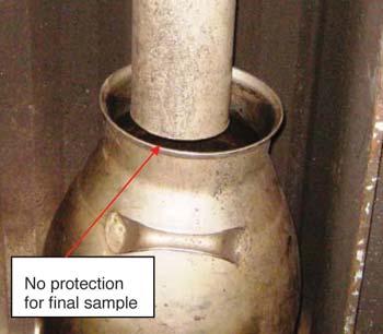
- In the case of two loadout inspections on behalf of utilities, observations were made regarding the final sample containers not being airtight or protected and resulting in the potential for unaccounted for moisture loss and a likely bias.
- In Figure 2, the final sample falls into the “milk can” container, is unprotected and open to contamination and moisture loss.
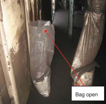
- In Figure 3, the final sample bag was found open after the first half of the train was loaded. Site personnel seemed to be unaware of the possible problem with leaving the bag standing open. More training is needed.
- In Figure 2, the final sample falls into the “milk can” container, is unprotected and open to contamination and moisture loss.
- An inspection of a sampling system and related processes was made on behalf of a utility. An observation was made that the system’s bias test was conducted differently from the routine sample handling method.
The recent bias test report was reviewed. The secondary sampler of this two-stage system has the capability to deliver the increments to two final sample containers located on opposite sides, A and B of the secondary sample belt feeder. During the bias test, the A and B sample was combined for analysis. The routine operational procedure of the system was to take one side—the A sample for the “in-house” analysis and the other side—the B sample was sent to the independent laboratory for the utility’s analysis. If the two sides are to be used independently, the system operating parameters must be set to provide the minimum number of increments per ASTM for each side and the system must be tested during the bias test to verify that this practice, i.e., each side is “unbiased.”
Regulatory Authority & Quality Assurance
When testing a belt scale or a batch weighing system there is a regulatory authority that certifies the operation of the weighing system. With mechanical sampling, the authority is the language in the coal supply agreement. Coal supply agreements have some specificity as to sampling using the phrase “according to ASTM” to describe issues related to sampling and operation of a mechanical sample. A bias test, extraction table, sampling ratio charting, review of operational and maintenance procedures and other parameters may be cited in the agreement. Many agreements may not cite the new ASTM sampling practice, D7430.
Specific analysis methods may or may not be specified. More specificity in coal supply agreements is recommended to ensure that the preferred quality assurance parameters will not be ignored. The process to ensure the correct sample is collected and analyzed is not solely to use a bias test as the ultimate authority. The bias test is only part of the process. After the bias test, what happens in the intervening period between bias tests?
A program of sampling system quality assurance can provide confidence to the contract parties to ensure that a good faith effort is made. An agreed upon program can outline processes for contract samples to be collected in the proper manner and the processes from sample collection to laboratory analysis be known i.e., no surprises. A competent program contains the following elements:
- An initial commissioning or system improvement program for the mechanical sampler such as the Seven Step program, which includes inspection, sampling ratio charting and bias testing.
- Preventive maintenance—ensuring the mechanical stability of the sampling system improves system availability.
- Written procedures—documentation demonstrates a proactive way to ensure that the program is known to all personnel involved and the contractual partner.
- Sampling may be conducted at origin and destination. For the sampling processes that are not contractual to have a competent challenge, similar quality assurance practices must be used. Ignoring quality assurance because a system is not the contractual sampling system can take away the opportunity to challenge the contractual sample.
- Periodic inspection, including evaluation using an extraction table.
- Sample crusher product sieve analysis.
Seven Step Program for System Improvement or Commissioning
It is risky to “jump into” a bias test as soon as the first system is operational. The plan below is a measured action plan to ensure successful system startup and improvement of an existing system.
- Inspect the system while in service and while taken out of service. Include inspections of the pneumatic, hydraulic, and electric drive components, cutters, chute work, crusher components and PLC function. Measure all cutter speeds, cutter operating intervals and sample flow rates. Prepare a detailed description of all mechanical problems found.
- Fix the mechanical problems found during the inspection.
- Prepare a sample extraction table describing how the sampling system is now operating. Make the corrections to the sampling parameters necessary to eliminate bias. This is critical. Prepare a corrected sample extraction table which includes the design sampling ratio.
- Begin control charting the sampling ratio.
- Identify and fix causes of out-of-control conditions. Causes include design problems, mechanical problems and operator problems. Until you have a stable, in-control system, you will not have reliable sample results.
- After a stable condition has been reached as indicated by 20 or more successive sampling ratios being in control, check the coefficient of variation (% CV) of the sampling ratio. If the % CV is greater than 15, identify and fix the causes of excessive variation.
- Continue to chart the sampling ratio and take action when indicated by the charts. After the system is stable, the % CV is less than 20 (actually, for some systems less than 10 is an achievable goal), and the average of 20 or more sampling ratios average observed value is within 10% of the design ratio, bias test the system for the purpose of documenting your successful improvement process.
Extraction Tables
To properly understand the operation of a sampling system an extraction table is essential to verify sampling system operating parameters and system flow rates. By using an extraction table, the system operation can be mathematically evaluated. Also, one can exercise “what ifs” such as the impact of increased or decreased tons per hour flow rate to the primary sampler.
By using the extraction table, as preparation plant personnel use the plant flow sheet to evaluate flow rates and equipment capacities, the sampling system inspector can formulate mathematical recommendations versus estimates, which can cost time and money if not correct. The extraction table also results in total sample mass and design sampling ratio values. This evaluation and planning tool is very useful, but is not discussed in ASTM D7430. Table 2 displays an as-found extraction versus a recommended extraction.
Table 2: Barge Unloading Two-stage Sampling System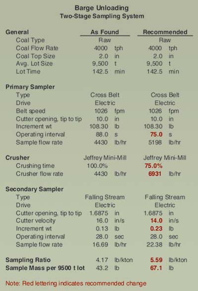
Sampling Ratio Control Charts
Use of the sampling ratio control chart is recommended in ASTM D7430. Currently some coal supply agreements specify their use. These charts have rules and limits and are process control charts, which provide mathematical evidence that the system is operating correctly. The example control chart in Table 3, which is very easy to use, is the result of a visual basic adding to Excel. By using the chart consistently, one can verify the correct extraction of increments from the coal stream to be sampled. Also one can show consistent operation and accumulate an operational history to explain special cause occurrences such as crusher pluggage or other issues. In this manner the operator is provided with current information as to each sample’s conformance to the ASTM limits stated in D7430 i.e., whether the system is within the 15% limit for percent coefficient of variation and 10% difference between the design (calculated) sampling ratio and the average observed sampling ratio.
Table 3: ACME Plant Example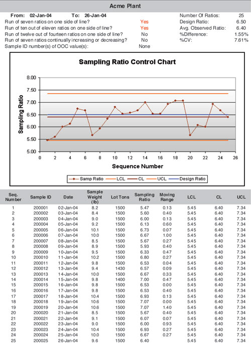
Coal sampling systems are mechanical devices that operate in a predictable way to extract and accumulate increments from coal streams. The risks presented and mathematical methods for evaluation of mechanical sampling systems presented above can provide the confidence of correct system operation. These methods enable evidence to be provided to inspectors, management and others who may question or just need assurance of the system’s correct operation.
Using these methods we raise the level of what constitutes a “good” sampling system from “doesn’t plug up and puts coal in the bag.” to one evaluated using mathematical methods. This prevents issues being presented by auditors or inspectors which can surprise and embarrass operation and management personnel.
Renner is the manager of inspection and performance testing for SGS Minerals Services. This article was adapted from a presenation he gave at Coal Prep 2012. He can be reached at: chuck.renner@sgs.com.